3D Vision Computing with Mobile Phone Images
Published:

1. Find the focal length of the handphone
Setup on which the code was tested
- python==3.7
- numpy==1.19.2
1.1 Process of calculating the focal length
Given a camera in a 3D scenario with unknown intrinsic parameters, its focal length can be estimated with the following method. As is shown in Fig. 1, 𝐴 and 𝐵 represent two actual points on a wall plane while 𝑎 and 𝑏 represent the corresponding pixels projected to the image plane of the camera which is placed at position 𝑂, facing to the wall.
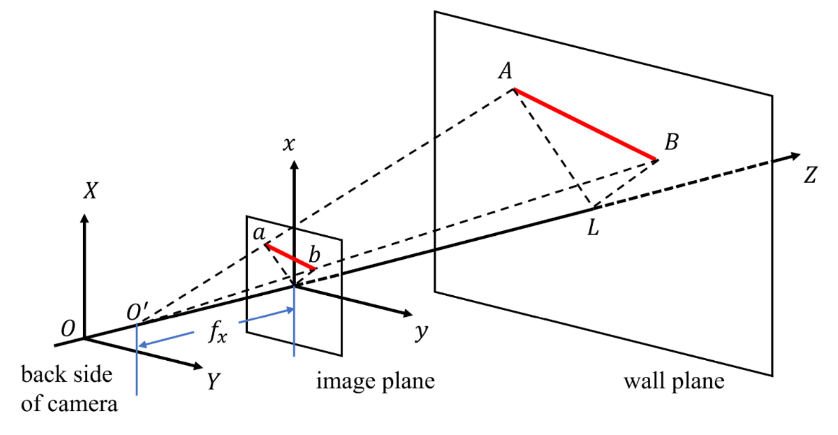
Fig.1 Diagram of camera imaging process
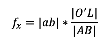
We denote the pinhole of the camera as 𝑂 , and the intersection point of the 𝑍 axis and the wall plane as 𝐿. According to projective geometry, the focal length of the camera can be derived as:
1.2 Experiment and result
In our experiment, we chose the shoulder breadth of a real person as the measurement target (shown in Fig. 2).
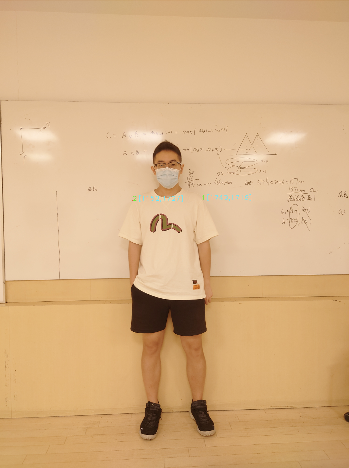
Fig.2 Actual experiment situation
During the measurement process, the person leant against the whiteboard behind him and the reference points were marked on the boundary point of the two shoulders on the whiteboard. Then a picture is taken by the handphone (Sony Xperia 1 II) which is placed facing to the whiteboard at a distance.
Firstly, two distances are measured in real-world: the breadth of the person’s shoulder (|𝐴𝐵|), and the distance between the handphone and the whiteboard (|𝑂𝐿|). After several tests, the average of the two measures are calculated:
Secondly, in order to caclulate the pixel distance between the corresponding two points on the image plane, a python script using OpenCV(shown in Appendix) was used to conveniently get pixel positions on image. In this way we get the location of the 2 points as a = (1152,1727), b = (1743, 1719), Hence:

Furthermore, Fig. 4 proves that we turned off the auto focusing during this measurement, so the experimental result data is valid.

Fig.4 Picture of the shooting process
2. Find the rotation of the handphone
2.1 Process of calculating the rotation
The general process of finding the transformation, including translation and rotation, of the camera from two images is shown below.
Fig. 5 shows that the camera took two pictures at two different locations C1 and C2, and the corresponding points are 𝑥1, 𝑥2, . . . , 𝑥𝑛 and 𝑝1, 𝑝2, . . . , 𝑝𝑛 respectively. 𝑋 ,𝑋 ,…,𝑋 and 𝑃 ,𝑃 ,…,𝑃 are the points projected on the image plane of the 12𝑛12𝑛 camera.
To find the transformation of the camera between these two positions, we introduce two approaches, the SVD approach and the quaternion approach.
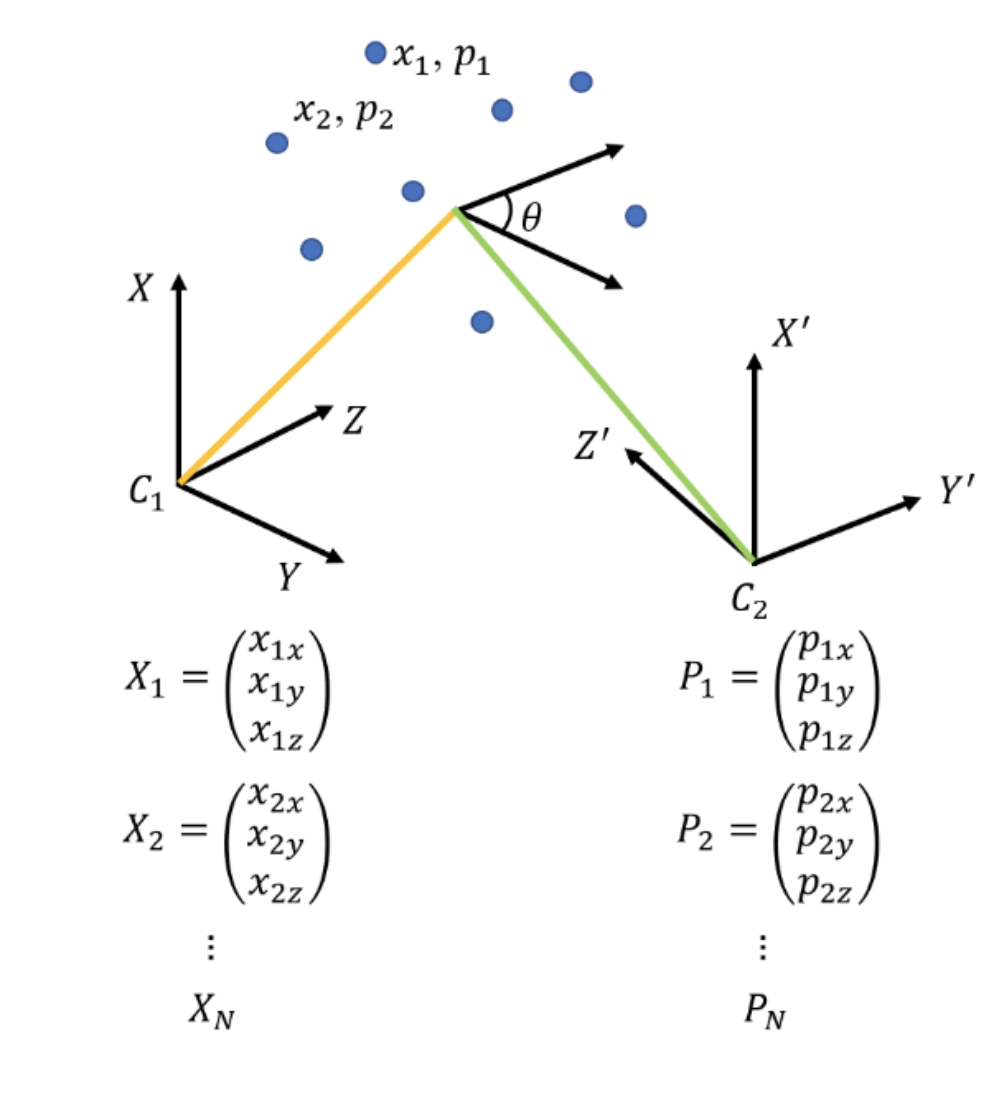
Fig.5 Images captured at different locations
2.2 The SVD approach
We want to find the optimal translation t and the rotation R that minimize the sum of the squared error:

Where xi and pi are the corresponding points, and Np is the number of the point-pairs.
Then the centers of mass of the two point sets are calculated (X_n and P_n).
Subtract the corresponding center of mass from every point in the two point sets and get the resulting point sets (X_dev and P_dev).
Let W = X_dev.T @ P_dev and perform singular value decomposition(SVD) on W by:
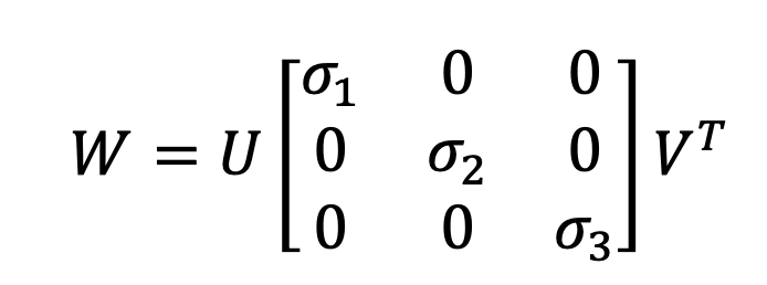
If rank (W) = 3 , then the optimal solution of E(R, t) is unique and is given by:
The rotation angle and the rotation axis l are given by:
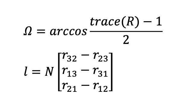
2.3 Experiment and result
We took two pictures of a corridor, shown in Fig 6.
The two pictures were taken at the same location, and we carefully rotated the handphone for 10 degrees(as the ground truth of this experiment). In these two pictures, we picked 8 pairs of distinguishing points, and their coordinates in pixels were shown in the Fig 6.
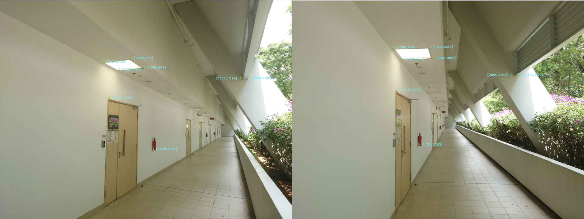
Fig.6 Pictures of a corridor in different angle (gt=10deg)
Using the SVD method, We got the rotation angle and the rotation axis l:

2.4 Experiment result analysis
From the experiment, the rotation angle calculated using SVD approach is 11.19 degrees, and the rotation angle calculated using quaternion approach is 11.65 degrees, while the ground truth is 10 degrees. They have 1.19 and 1.65 degrees error respectively.
There are two reasons causing this error. Firstly, the measurement error. The distance measured in this experiment, and the ground truth of rotation angle, both can introduce error to the final result. Secondly, the model approximation. During the calculation of focal length in Section I, the physical camera center on the back side of the handphone( O ), and the actual optical center of the camera( O’ ) are considered the same. This approximation can cause error.
Among these two aspect, we believe the measurement error has greater effect on the result, especially the ground truth of the rotation angle. We didn’t have a tripod for the phone to rotate the phone precisely, so the actual ground truth may not be 10 degree.
3. Conclusion
In this work, the focal length of a photo camera was calculated through a series of steps. The rotation angle was obtained through two different methods: SVD approach and quaternion approach. And the reasons that may cause the angle error were analyzed after the experiments.
Issues
The above is the description of the work on Focal Length calculation and SVD method to calculate the R and l for 3D posing estimation. If you encounter unclear or controversial issues, feel free to contact Leslie Wong.

